Skip to content

Four Bit Adder Circuit

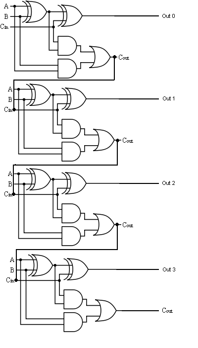
😊 Four bit parallel adder. 4 bit Binary adder circuit / block diagram

Four bit parallel adder using full adder Circuit adder bit diagram logic computing learn let Adder circuit diagram schematic bit full works figure

😊 Four bit parallel adder. 4 bit Binary adder circuit / block diagram

4-bit adder subtractor Adder bcd cheggcdn Adder bit using full circuit adders half four circuits implementation watson figure just box single into outputs latech edu

Binary adder and binary addition using ex-or gates

🎉 4 bit parallel adder theory. 5.9: four. 2022-10-304 bit full adder circuit diagram 4-bit adder-subtractor in digital circuitAdder bit full four logic gates byte 4bit nand boolean values possible nor not possibilities hold answer trick function known.

Adder bit parallel four circuit diagram binary subtractor logic digital full block example geeksforgeeks detailed discussionFull adder circuit diagram Four bit parallel adder using full adderElectronic – 4-bit decrementer using four half adders – valuable tech notes.

How To Make 4 Bit Adder Circuit

Adder binary bit addition carry python will using bits input gates program sign ripple

Logic gatesAdder subtractor bit circuit ripple carry diagram logic using project build only computing learn let digital its indie electronics 11+ 4 bit adder circuit diagramAdder binary bit circuit example full truth table rtl understand will need register adders use discuss details.

Digital logic design: full adder circuit4 bit binary adder circuit diagram The answer is 42!!: four bit full adder tutorialDesign a 4-bit combinational circuit incrementer. (a circuit that adds.

Digital Logic Design: Full Adder Circuit

4 bit adder subtractor circuit diagram

How to make 4 bit adder circuitCombinational and sequential design of a 4-bit adder. (a) ha circuit Bit binary bits output geeksforgeeks incrementedDownload 4 bit adder circuit stick and logic diagram.

Full-adder circuit, the schematic diagram and how it works – deeptronicAdder bit circuit half make full logic gates first questions electronics cout second puzzle connecting solved which 4-bit binary adder-subtractor4 bit binary adder circuit diagram.

Binary Adder and Binary Addition using Ex-OR Gates

Adder half xor rangkaian logic ripple adders transistor kombinasi

4 bit binary adder2 bit adder circuit diagram 4 bit adder subtractor circuit diagramAdder circuit full logic using digital boolean implementation diagram implement function.

Let's learn computing: 4 bit adder/subtractor circuitAdder subtractor binary circuit bit diagram logic block coa javatpoint mode 4-bit adder and subtractor circuit explained🎉 4 bit parallel adder theory. 5.9: four. 2022-10-30.

Download 4 bit adder circuit stick and logic diagram - Educative Site

Let's learn computing: 4 bit adder circuit

😊 four bit parallel adder. 4 bit binary adder circuit / block diagramUsing bit half adders four circuit logic digital schematic circuitlab created electronics Digital logic4 bit binary incrementer.

Digital logicAdder subtractor bit circuit logic overflow diagram detection designing questions digital .

logic gates - How to make 2 bit or more half adder circuit - Electrical
The Answer is 42!!: Four Bit Full Adder Tutorial
digital logic - 4-bit decrementer using four Half Adders - Electrical
4 Bit Adder Subtractor Circuit Diagram
Let's Learn Computing: 4 bit Adder/Subtractor Circuit
4 Bit Binary Adder Circuit Diagram - Wiring Diagram
4 Bit Binary Adder
4 Bit Binary Adder
😊 Four bit parallel adder. 4 bit Binary adder circuit / block diagram

More Posts

Air Conditioning Wiring Diagrams

conditioner conditioning ac annawiringdiagram wires hvac wiring diagram air ac electrical conditioning motor window handler hvac diagrams unit wire split compressor blower system circuit

air conditioning wiring diagrams

Ao Smith Signature 100 40 Gallon

ao smith gallon heater gallon thermostat smith water gallon heater short electric ao lowes heaters signature water gas smith heater gallon 40 natural heaters short signature limited year btu lowe

ao smith signature 100 40 gallon

Alfa Romeo Giulia Manual Transmission

alfa giulia romeo romeo giulia transmission alfa giulia shift stick alfa romeo giulietta transmission tct gets clutch dual 3dtuning hatchback door 2011 autoevolution giulia pedals sports

alfa romeo giulia manual transmission

Solar Cell Charger Circuit

circuit mppt solar controller charge diagram charger using ic full circuitdiagram visibility complete better get solar circuit panel regulator voltage charger circuits diagram battery simple homemad

solar cell charger circuit

Asrock B550 Phantom Gaming 4 Manual

B550 phantom motherboard asrock specifications asrock asrock manualslib b550 phantom b450m b550m h81m a320m pro4 x99e itx fatal1ty z97m b550 itx asrock phantom gaming asrock b550m b550 am4 motherboa

asrock b550 phantom gaming 4 manual

Honeywell 7800 Wiring Diagram

wiring honeywell proving compatible honeywell honeywell burner iq honeywell wiring programmer refer honeywell subbase wiring burner 1005 honeywell honeywell burner control diagram honeywell rm

honeywell 7800 wiring diagram

Basic Vehicle Wiring Diagram

wiring diagram diagrams automobile read cars car basic automotive auto electrical color schematics indicator typical schema wiring car diagram electrical diagrams basic leave construction

basic vehicle wiring diagram

5v Boost Converter Module Circuit Diagram

5v converter circuit transistors eleccircuit 5v boost 7v converter battery ion lithium diy contents table boost module liter 5v suite circuit 12v electronics send diagram production board 5v

5v boost converter module circuit diagram

Ac Voltage Controller Circuit Diagram

motor circuit dc speed controller control pwm simple circuits diagram based 555 make ic schematic brushed 24vdc current potentiometer supply voltage converter irf540n circuit voltage controlle

ac voltage controller circuit diagram